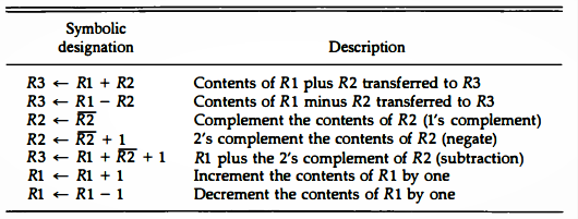
- Arithmetic micro operations are arithmetic operations such as Addition and Subtraction that are performed on the value of a register.
- The simplest form of arithmetic micro operations are increment and decrement.
- Increment is nothing but adding value 1 to the existing content of the register. Similarly decrement will reduce the existing value of a register by 1.
- These micro operations are implemented with a combinational circuit or with a binary up-down counter.
- The symbolic representation of some of the micro operations are shown in the above table along with the description
- Here is an arithmetic micro operation, which is represented using the Register Transfer Language (RTL) as follows:
- It specifies the add micro operation, that adds the contents of register R1 with the contents of register R2, and the sum be transferred to register R3.
- The arithmetic operations of multiply and divide are not listed in above Table.
- These two operations are valid arithmetic operations but are not included in the basic set of micro operations.
- In most computers, the multiplication operation is implemented with a sequence of add and shift microoperations.
- Division is implemented with a sequence of subtract and shift micro operations.
Implementing Micro Operation - Add:
- To implement the add microoperation with hardware, we need the registers that hold the data and the digital component that performs the arithmetic addition.
- The digital circuit that forms the arithmetic sum of two bits and aprevious carry is called a full-adder
- The digital circuit that generates the arithmetic sum of two binary numbers of any length is called a binary adder.
4-bit Binary Adder
- The binary adder is constructed with full-adder circuits connected in cascade, with the output carry from one full-adder connected to the input carry of the next full-adder.
- The augend bits of A and the addend bits of B are designated by subscript numbers from right to left, with subscript 0 denoting the low-order bit.
- The carries are connected in a chain through the full-adders.
- The input carry to the binary adder is C0 and the output carry is C4
- The S outputs of the full-adders generate the required sum bits.
An n-bit Binary Adder:
- An n-bit binary adder requires n full-adders.
- The output carry from each full-adder is connected to the input carry of the next-high-order full-adder.
- The n data bits for the A inputs come from one register (such as R1), and the n databits for the B inputs come from another register (such as R2).
- The sum can be transferred to a third register or to one of the source registers (R 1 or R2), replacing its previous content.
Implementing Micro Operation - Subtract:
- The Subtraction micro-operation can be done most conveniently by meansof complements, i.e., taking the 2's complement of addend bits and adding it to the augend bits
- For example, the subtraction A - B can be done by taking the 2's complement of B and adding it to A.
- The 2's complement can be obtained by taking the 1' s complement and adding one to the least significant pair of bits.
- The 1's complement can be implemented with inverters and a one can be added to the sum through the input carry.
- This adder-subtractor (subtraction through addition) operation can be combined into one common circuit by including an exclusive-OR gate with each full-adder
4-bit adder-subtractor:
- A 4-bit adder-subtractor circuit is shown in below figure.
- The mode input M controls the operation. When M = 0 the circuit is an adder and when M = 1 the circuit becomes a subtractor
- Each exclusive-OR gate receives input M and one of the inputs of B.
- When M = 0, we have B ⊕ 0 = B. The full-adders receive the value of B, the input carry is O, and the circuit performs A plus B
- When M = 1, we have B ⊕ 1 = B' and C0 = 1. The B inputs are all complemented and a 1 is added through the input carry.
- The circuit performs the operation A plus the 2's complement of B
Binary Incrementer:
- The increment microoperation adds one to a number in a register.
- For example, if a 4-bit register has a binary value 0110, it will go to 0111 after it is incremented.
- Every time the count enable is active, the clock pulse transition increments the content of the register by one.
- The diagram of a 4-bit combinational circuit incrementer is shown in Fig. 4-8.
- One of the inputs to the least significant half-adder (HA) is connected to logic-1 and the other input is connected to the least significant bit of the number to be incremented.
- The output carry from one half-adder is connected to one of the inputs of the next-higher-order half-adder.
- The circuit receives the four bits from A0 through A3 adds one to it, and generates the incremented output in S0 through S3.
- The output carry C4 will be 1 only after incrementing binary 1111. This also causes outputs S0 through S1 to go to 0.


